Compare commits
2 Commits
| Author | SHA1 | Date | |
|---|---|---|---|
|
|
927ef2353c | ||
|
|
703130307c |
Binary file not shown.
|
Before Width: | Height: | Size: 378 KiB |
@@ -169,11 +169,11 @@ endfunction
|
||||
// =========================================================================
|
||||
// Clamp a wider signed value to [-7, +7]
|
||||
function signed [3:0] clamp_gain;
|
||||
input signed [5:0] val; // 6-bit: covers [-22,+22] (max |gain|+step = 7+15)
|
||||
input signed [4:0] val; // 5-bit to handle overflow from add
|
||||
begin
|
||||
if (val > 6'sd7)
|
||||
if (val > 5'sd7)
|
||||
clamp_gain = 4'sd7;
|
||||
else if (val < -6'sd7)
|
||||
else if (val < -5'sd7)
|
||||
clamp_gain = -4'sd7;
|
||||
else
|
||||
clamp_gain = val[3:0];
|
||||
@@ -246,15 +246,15 @@ always @(posedge clk or negedge reset_n) begin
|
||||
// Use inclusive counts/peaks (accounting for simultaneous valid_in)
|
||||
if (wire_frame_sat_incr || frame_sat_count > 8'd0) begin
|
||||
// Clipping detected: reduce gain immediately (attack)
|
||||
agc_gain <= clamp_gain($signed({agc_gain[3], agc_gain[3], agc_gain}) -
|
||||
$signed({2'b00, agc_attack}));
|
||||
agc_gain <= clamp_gain($signed({agc_gain[3], agc_gain}) -
|
||||
$signed({1'b0, agc_attack}));
|
||||
holdoff_counter <= agc_holdoff; // Reset holdoff
|
||||
end else if ((wire_frame_peak_update ? max_iq[14:7] : frame_peak[14:7])
|
||||
< agc_target) begin
|
||||
// Signal too weak: increase gain after holdoff expires
|
||||
if (holdoff_counter == 4'd0) begin
|
||||
agc_gain <= clamp_gain($signed({agc_gain[3], agc_gain[3], agc_gain}) +
|
||||
$signed({2'b00, agc_decay}));
|
||||
agc_gain <= clamp_gain($signed({agc_gain[3], agc_gain}) +
|
||||
$signed({1'b0, agc_decay}));
|
||||
end else begin
|
||||
holdoff_counter <= holdoff_counter - 4'd1;
|
||||
end
|
||||
|
||||
@@ -7,6 +7,7 @@
|
||||
[](https://github.com/NawfalMotii79/PLFM_RADAR)
|
||||
[](https://github.com/NawfalMotii79/PLFM_RADAR/pulls)
|
||||
|
||||
|
||||
|
||||
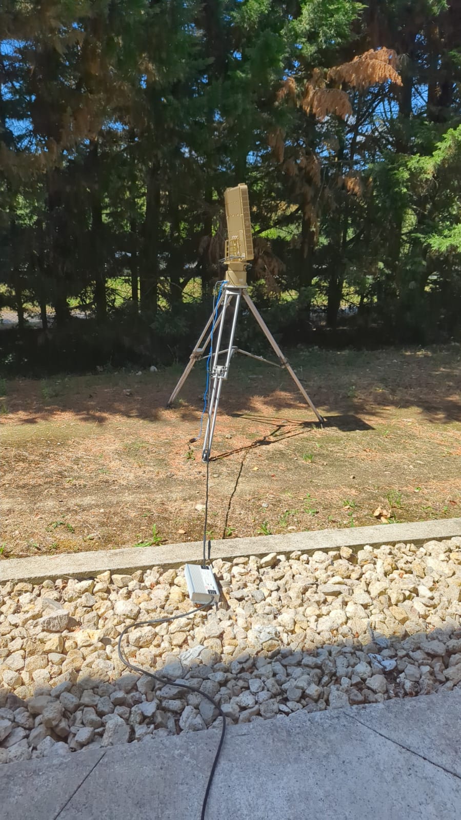
AERIS-10 is an open-source, low-cost 10.5 GHz phased array radar system featuring Pulse Linear Frequency Modulated (LFM) modulation. Available in two versions (3km and 20km range), it's designed for researchers, drone developers, and serious SDR enthusiasts who want to explore and experiment with phased array radar technology.
|
||||
|
||||
@@ -46,7 +47,7 @@ The AERIS-10 main sub-systems are:
|
||||
|
||||
- **Main Board** containing:
|
||||
- **DAC** - Generates the RADAR Chirps
|
||||
- **2x Microwave Mixers (LTC5552)** - For up-conversion and IF-down-conversion
|
||||
- **2x Microwave Mixers (LT5552)** - For up-conversion and IF-down-conversion
|
||||
- **4x 4-Channel Phase Shifters (ADAR1000)** - For RX and TX chain beamforming
|
||||
- **16x Front End Chips (ADTR1107)** - Used for both Low Noise Amplifying (RX) and Power Amplifying (TX) stages
|
||||
- **XC7A50T FPGA** - Handles RADAR Signal Processing on the upstream FTG256 board:
|
||||
@@ -91,7 +92,7 @@ The AERIS-10 main sub-systems are:
|
||||
### Processing Pipeline
|
||||
|
||||
1. **Waveform Generation** - DAC creates LFM chirps
|
||||
2. **Up/Down Conversion** - LTC5552 mixers handle frequency translation
|
||||
2. **Up/Down Conversion** - LT5552 mixers handle frequency translation
|
||||
3. **Beam Steering** - ADAR1000 phase shifters control 16 elements
|
||||
4. **Signal Processing (FPGA)**:
|
||||
- Raw ADC data capture
|
||||
|
||||
Reference in New Issue
Block a user